
Page 16 - machining_titanium_05_2019
P. 16
MILLING TITANIUM 7. In process planning, check the possibility of milling titanium while it is in a soft condition.
6. Titanium alloys, especially their more difficult-to-machine grades, feature significant specific cutting
force, which leads to high mechanical loading of the cutting edge. Titanium’s “springiness” boosts
vibrations, particularly in rough milling with considerable machining allowance. This means that effective
cutting under such conditions stipulates high rigidity of the whole technological system, and stiffness
of a machine tool, proper work- and tool holding, and the tool overhang may be crucial.
Heat treatment and age-hardening make titanium much more difficult to machine.
8. High-pressure coolant (HPC) supply can dramatically improve milling efficiency*.
9. Milling deep pockets and cavities requires a high tool overhang. When planning
machining operations, possible alternatives are to use several milling cutters with
different overhangs, or several assemblies, in which the same cutters are mounted
in toolholders with various neck lengths, instead of one long-reach tool.
10. High feed milling (HFM, fast feed milling) may be a viable alternative to traditional heavy-
duty rough milling. HFM titanium is suitable for machining tools with slow table drive due
to the feed speed being considerably lower compared to the values necessary for HFM
steel. However, applying the alternative requires machines with a rigid spindle unit.
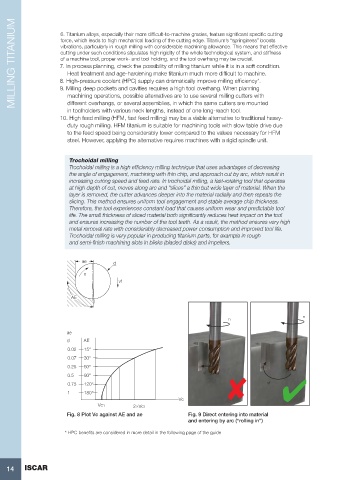
Trochoidal milling
Trochoidal milling is a high efficiency milling technique that uses advantages of decreasing
the angle of engagement, machining with thin chip, and approach cut by arc, which result in
increasing cutting speed and feed rate. In trochoidal milling, a fast-rotating tool that operates
at high depth of cut, moves along arc and “slices” a thin but wide layer of material. When the
layer is removed, the cutter advances deeper into the material radially and then repeats the
slicing. This method ensures uniform tool engagement and stable average chip thickness.
Therefore, the tool experiences constant load that causes uniform wear and predictable tool
life. The small thickness of sliced material both significantly reduces heat impact on the tool
and ensures increasing the number of the tool teeth. As a result, the method ensures very high
metal removal rate with considerably decreased power consumption and improved tool life.
Trochoidal milling is very popular in producing titanium parts, for example in rough
and semi-finish machining slots in blisks (bladed disks) and impellers.
ae d
n
vf
AE
n
n
ae
d AE
0.02 15°
0.07 30°
0.25 60°
vf
0.5 90°
0.75 120° vf
1 180°
Vc
Vc1 2×Vc1
Fig. 8 Plot Vc against AE and ae Fig. 9 Direct entering into material
and entering by arc (“rolling in”)
* HPC benefits are considered in more detail in the following page of the guide
14 ISCAR