
Page 15 - machining_titanium_05_2019
P. 15
General Guidelines for Milling Titanium
When milling titanium, a manufacturer tries to obtain the most effective milling technique and the
appropriate tool. Best production practices have already developed general recommendations to
successfully complete these tasks, in order to overcome the main difficulties in cutting titanium MILLING TITANIUM
while ensuring acceptable productivity and tool life. Even though the technique and the tool
relate to each other, the recommendation may be considered with respect to each separately.
Milling Technique
Milling technique or milling strategy determines the tool path and the
“depth of cut (ap) – width of cut (ae)” relation. In choosing the most suitable
machining strategy, the following points are taken into consideration:
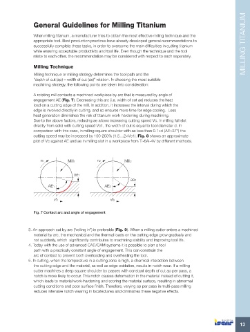
A rotating mill contacts a machined workpiece by arc that is measured by angle of
engagement AE (Fig. 7). Decreasing this arc (i.e. width of cut ae) reduces the heat
load on a cutting edge of the mill. In addition, it increases the interval during which the
edge is involved directly in cutting, and so ensures more time for edge cooling. Less
heat generation diminishes the risk of titanium work hardening during machining.
Due to the above factors, reducing ae allows increasing cutting speed Vc. In milling full slot
directly from solid with cutting speed Vc1, the width of cut is equal to tool diameter d. In
comparison with this case, in milling square shoulder with ae less than 0.1×d (AE≈37°) the
cutting speed may be increased by 150-200% (1.5…2×Vc1). Fig. 8 shows an approximate
plot of Vc against AE and ae in milling slot in a workpiece from Ti-6Al-4V by different methods.
n1 Mill1 n2 Mill2
ae1
ae2
AE1 AE2
vf1 vf2
Fig. 7 Contact arc and angle of engagement
3. An approach cut by arc (“rolling in”) is preferable (Fig. 9). When a milling cutter enters a machined
material by arc, the mechanical and the thermal loads on the cutting edge grow gradually and
not suddenly, which significantly contributes to machining stability and improving tool life.
4. Today with the use of advanced CAD/CAM systems it is possible to plan a tool
path with a practically constant angle of engagement. This can constrain the
arc of contact to prevent both overloading and overheating the tool.
5. In cutting, when the temperature in a cutting zone is high, a chemical interaction between
the cutting edge and the material, as well as edge oxidation, results in notch wear. If a milling
cutter machines a deep square shoulder by passes with constant depth of cut ap per pass, a
notch is more likely to occur. This notch causes deformation in the material instead of cutting it,
which leads to material work-hardening and scoring the material surface, resulting in abnormal
cutting conditions and poor surface finish. Therefore, varying ap per pass in multi-pass milling
reduces intensive notch wearing in located area and diminishes these negative effects.
13