
Page 4 - USER_GUIDE_WhisperLine
P. 4
CHATTER SUPPRESSION METHOD OF ISCAR ANTI-VIBRATION TOOLS
A mechanism is designed to preload the elastomers and therefore to modify the stiffness of
their equivalent spring. Modification of the spring stiffness causes a change of the DVA natural
frequency. The DVA system is tuned such that its natural frequency is brought close to that of
the tool without DVA. This is done in order to introduce a phase shift between the tool and the
DVA mass vibration, eventually causing attenuation of the oscillation amplitude of the tool.
mass
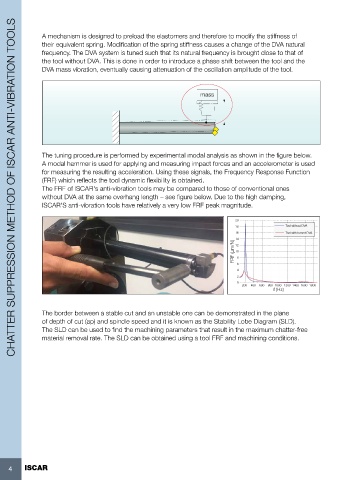
The tuning procedure is performed by experimental modal analysis as shown in the figure below.
A modal hammer is used for applying and measuring impact forces and an accelerometer is used
for measuring the resulting acceleration. Using these signals, the Frequency Response Function
(FRF) which reflects the tool dynamic flexibility is obtained.
The FRF of ISCAR's anti-vibration tools may be compared to those of conventional ones
without DVA at the same overhang length – see figure below. Due to the high damping,
ISCAR'S anti-vibration tools have relatively a very low FRF peak magnitude.
20
18 Tool without DVA
16 Tool with turned DVA
14
FRF ( m/N) 10 8
12
6
4
2
0
200 400 600 800 1000 1200 1400 1600 1800
f (Hz)
The border between a stable cut and an unstable one can be demonstrated in the plane
of depth of cut (ap) and spindle speed and it is known as the Stability Lobe Diagram (SLD).
The SLD can be used to find the machining parameters that result in the maximum chatter-free
material removal rate. The SLD can be obtained using a tool FRF and machining conditions.
4 ISCAR